


In design, the question often arises as to how you can design so that you do not have any problems later on, even in production. One way is to design structures during construction that later work better in manufacturing. Is this effective? Very often I would say no. Construction and manufacturing should be clearly separated. So how can I derive production-appropriate models from a normal assembly in Creo Parametric without having to use the original construction?
The answer is the usage of inheritance models.
To briefly illustrate this for you, we choose a PTC Creo welding assembly. We all know that we construct such components as an assembly, but these are later an item, because you can’t take them apart again without flex or saw.
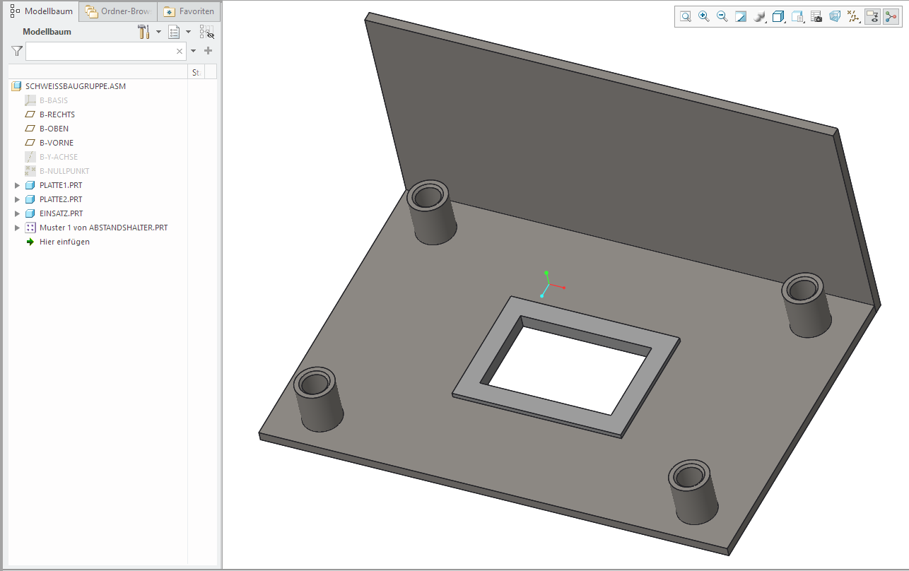
Our welding PTC Creo part consists of two plates: an edited Creo part that is welded with the floorboard, and 4 cylindrical spacers which are also spot-welded with the floor plate. Also take a closer look at the Creo model tree in the picture above. The model tree for this welding part is a flat structure in an Creo assembly.
Next, we assume that the production of this welding construction will go through a process. First, we have to weld the two plates together. Additionally, the stamping and the breakthrough for the centering section and the positions of the cylindrical spacers need to be produced. Finally, the accessories are welded with the plates. So how can we develop a process model for this welding assembly? Should simplified representations or family tables be used? What if the designer responsible for the design and documentation of this process does not have the rights to change the original models? Should the original Creo assembly be restructured?
Example 1 – Models with inheritance geometry
The simple answer is that we use PTC Creo process models with inheritance geometry. Let’s say, the first model that needs to be developed is the floor panel without processing and with some additional welding preparation.
To construct this model, we first create a new PTC Creo part.
We then select retrieve data, merge/inherit. This opens the dashboard to define this feature.
We select the icon for open folders and select the original sheet part as shown below.

Now, we open the folder or the PTC Windchill work space and select the original sheet part.
We assemble the model to standard.
Next, we choose the icon to switch the function to inheritance, as shown below.

By switching the function to inheritance, all construction elements (CE) of the original model are available in the new model. Therefore, we can suppress all CEs of the original model in the inherited model, without affecting the original Creo design model.
For this example, we need to suppress the editing CEs (that would be the cutout in the middle and the 4 reductions) to illustrate the plate in the initial state of our process.
Let’s complete the feature by ticking the green check mark on the Creo dashboard. Note that the geometry of the original plate is now in the new model. We expand the structure with the plus icon next to the inheritance feature in the model tree to show the original features as shown below.
With these CEs now displayed, the editing CEs can be selected and suppressed without affecting the original design model. Note the image below showing the model tree with the machining CEs and the resulting geometry.

The final step in creating this process model is to add edge preparation for the weld seam. This can be done, for example, with the standard functions of PTC Creo Parametric; this too is done without us influencing the original design model. In the image below, a simple round was added to show the edge preparation.

The process model is now complete and remains fully associative to the original design model.
Example 2 – Multiple Creo inheritance features
The same steps can be repeated to illustrate multiple process steps. In addition, multiple Creo inheritance features can be used to inherit geometry and CE formations of other parts. I’ll briefly show you another example of a process model for the next production step of our welding structure. Note the Creo model tree in the following example. The editing CEs in the first record were suppressed. A round was also added to illustrate the additional material added by the weld.

A single drawback remains with his process which is that the Creo parts need to be reassembled during the creation of the Creo merge/inheritance feature. Even with this small disadvantage, this procedure still has many advantages.
Here’s an example of step 3. Note that for this example the inherited model from step 2 was used to create the model for step 3. This nested, inherited structure allows us to display the CEs of the original plate and restore the editing CEs. In addition, dimensions can be added to this process model to show the dimensions and tolerances required. Note that the dimensions position the processing preparations of the second plate. This is a different dimensions scheme from what was used for the original design model.

The final step could be created in a similar way. Note that the dimensions are taken from the model in step 3.

Finally, the new Creo parts can be grouped together into an assembly to represent the process order.

This is just one of many techniques available in Creo Parametric (formerly ProE). To break down a structure and depict the manufacturing in process models. It has the advantage of not using Creo family tables or assembly functions that could cause parts to regenerate when retrieving. In addition, a designer can build a separate manufacturing structure without the design owner of the original design assembly having to restructure or adjust according to the production order.
This technique also works in an environment with PTC Windchill MPMLink. Windchill MPMLink allows the conversion of an engineering parts list or E-BOM into a production parts list or M-BOM. Once developed, these new Creo CAD models can be linked to downstream Windchill parts created with Windchill MPMLink. Here it becomes very quickly apparent that Creo, in combination with Windchill, has many advantages compared to other midrange CAD Systems like SolidWorks and Inventor.
This blogpost is more process-oriented. Nevertheless, it is a very interesting topic that makes manufacturing and construction easier. The methodology roughly shown here can also be applied to the spin industry. Especially when it comes to establishing the connection between the raw part and the finished part without the models influencing each other.
For this I also have a brief example.
Example 3 – Connect Creo Parametric designs without influencing each other
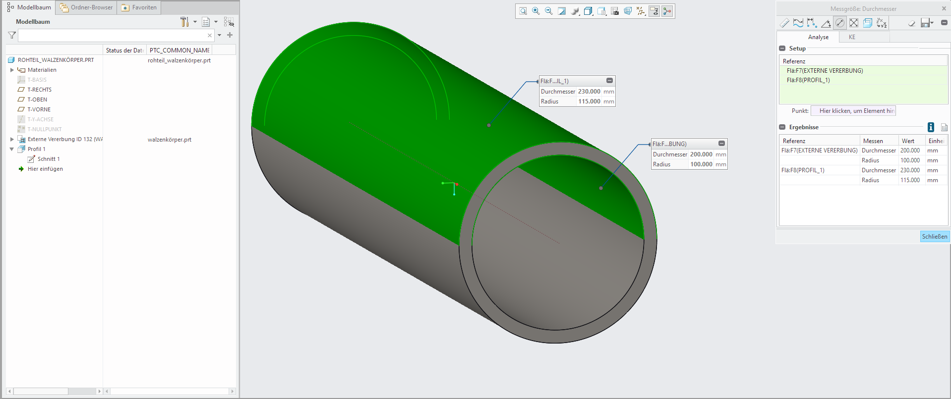
In roll construction the pure body of the rolls is often created from a pipe. So, we can first create the “finished” roll as an assembly. The structure here is like the one in the example above.

So, we now want a model that depicts the raw part. We are proceeding here as in the example above and creating a new part called raw Creo part. We inherit the finished roll body and depict the raw part as a pure measure. In our example, a standard of 5mm has been used.
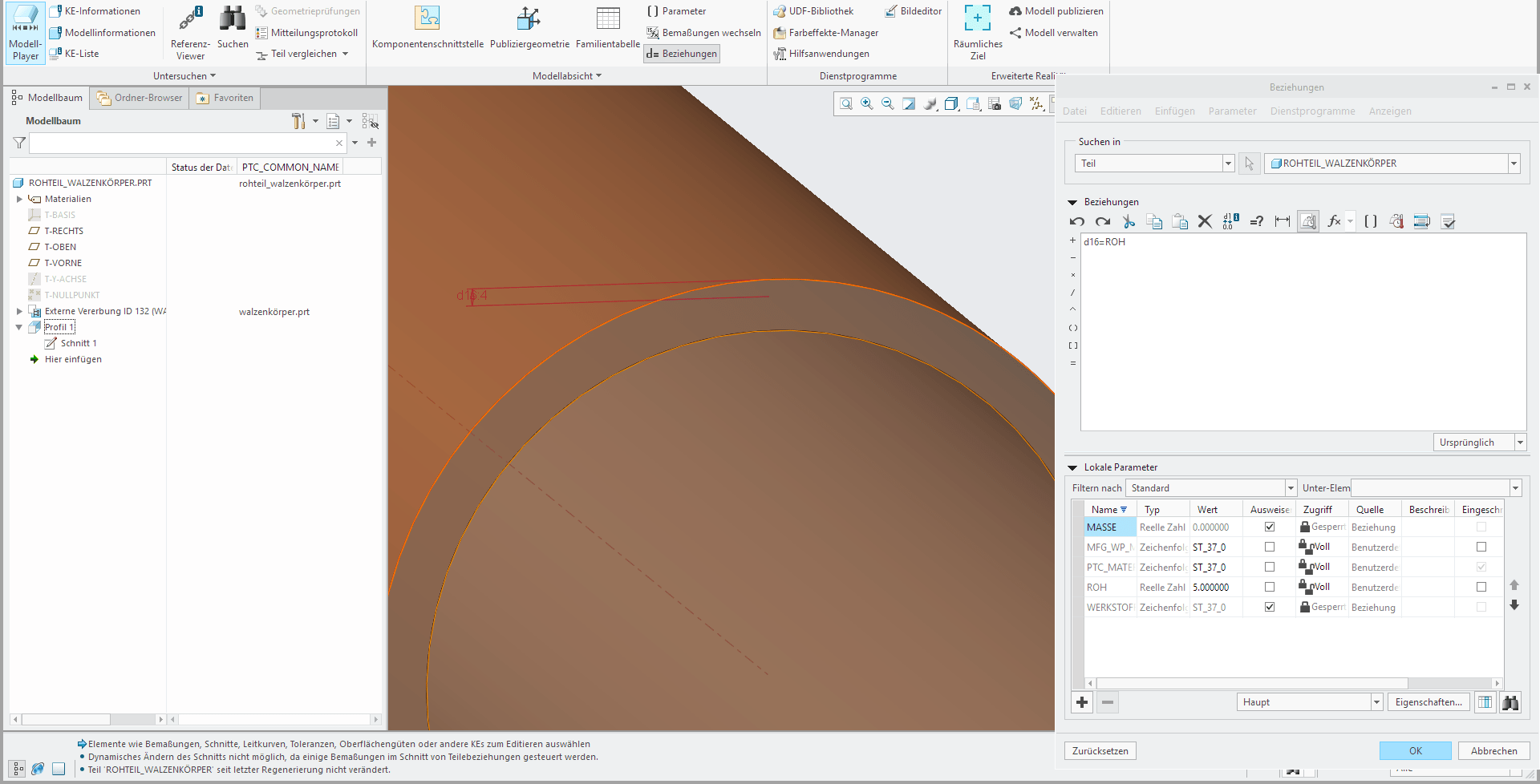
This measure can, for example, be entered as a fixed parameter so that it can be easily controlled. In our example the parameter “ROH” was simply directly related to “d14”.
In the same way, we could also control the raw parts length for the roll body. The roll shown here is also a welding assembly and, just like our example above, can be prepared for production accordingly. You can even go so far to create such assemblies as templates and therefore only control them via parameters, including the production drawings and customer drawing. Our in-house configurator product myPDS Configurator can also be used here. One advantage is, for example, that the sale can already provide all the necessary parameters in order to have a minimal design effort with recurring but minimally different products. The corresponding parameters only need to be loaded and the arbor is ready.
Why don’t you try inheritance models yourself? No Creo Parametric yet? Just talk to us or schedule a demo appointment with us. We are happy to present our examples live.
Best regards
Hans-Joachim Estler

