


When it comes to useful tools that can enhance teamwork efficiency, we usually think of the Product Lifecycle Management (PLM) systems. However, for the plastic part and mold designers, general-purpose PLM systems might not be satisfactory enough. The reason is that they cannot fully cooperate with the time-demanding yet complicated plastics mold development process, and it is usually too costly for small and medium-sized enterprises to adopt.
Plastics mold making has its unique design and manufacturing process. Frequent design changes and short delivery time make the situation even more challenging. Also, due to the high entry barriers of this industry, knowledge and skill gaps tend to occur. Under these circumstances, the preservation and inheritance of design experiences are extremely critical for enterprises today.
PLM focuses on managing the overall product lifecycle. It does not provide comprehensive features to bring design and engineering data together. The industry needs a platform to help acquire design and molding knowledge, and organize them in readable, searchable, and visualizable formats for future utilization. However, useful tools for tracing the design-optimization process, instant sharing and visualization of simulation results, comparing mold tryout and quality inspection data are missing in most PLM systems.
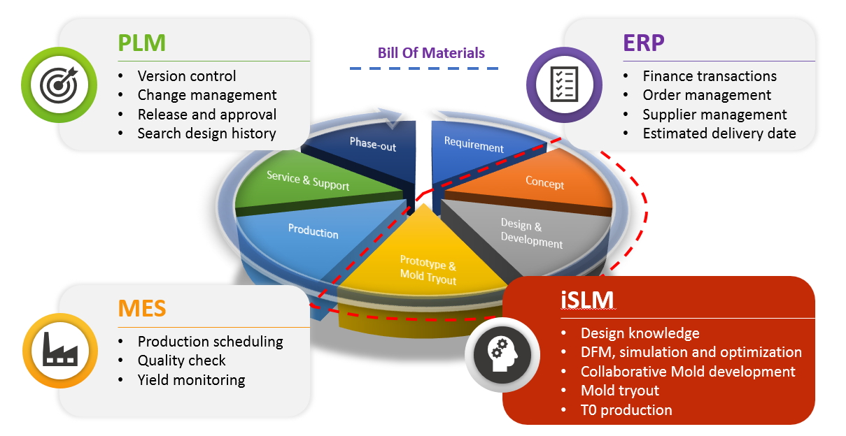
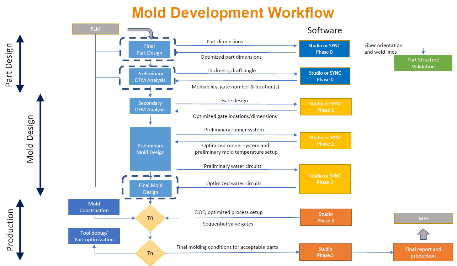
Every new plastic part and mold development involves many stages and different talents, such as product design, mold design, mold manufacturing, mold tryout, and production. When receiving a new project from an internal request or external customer via PLM, the design manager usually holds a preliminary Design for Manufacturing (DFM) meeting to determine the part requirements for preparing a quote. Numerous design and simulation iterations will then be performed in order to decide the gate number, locations, and sizes, improve flow balance, optimize runner system and water circuits, estimate cycle time and deal with potential shrinkage and warpage problems, etc. After the final mold design is concluded, the mold steel is cut and assembled for the first mold tryout (T0). Before T0, it would be very helpful to receive advice from simulations in order to optimize process conditions. Tool debug, part optimization, and mold tryouts are further proceeded to yield acceptable parts with competitive cost.
The above-mentioned process is critical to the long-term competitiveness of each company. However, different engineers oversee various stages in the whole process, and their data is usually stored in many different software, hardware, or file systems. To ensure a streamlined workflow and traceability, it is necessary to integrate and systemize these scattered data on one single platform.
Different from general PLM systems, iSLM is a web-based platform that can record various mold design data, such as material data, machine specifications, Moldex3D CAE analysis projects, mold information, mold tryout conditions, and molding results, etc. Users can access this data management platform through a browser on any device anywhere.
Only one click is needed to upload Moldex3D projects to iSLM. The system can automatically extract the representative information of project data, including run information, models, materials and processing conditions, etc. iSLM supports instant 3D visualization of analysis results. It is not needed to download the entire project back to users’ local desktop computers for visualization. Team members or clients can view the analysis data through browsers and collaborate in real-time.
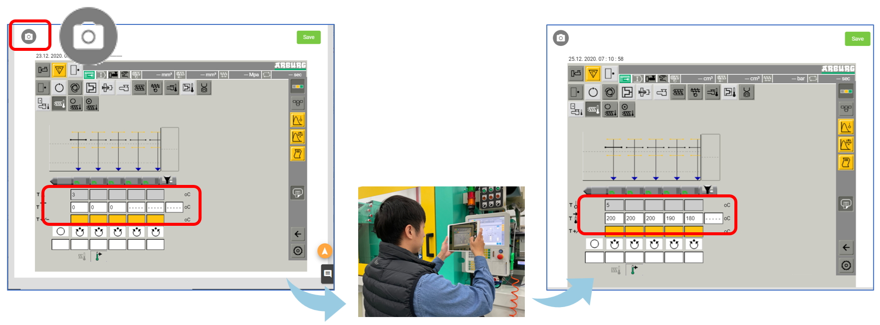
When recording process settings, it would make the most sense to connect the molding machines with iSLM via a Manufacturing Execution System (MES). However, due to the low level of digitalization of most injection molding shop floors, it is not uncommon that many factories are still recording process conditions on paper. Companies should not wait until all their machines are connected to the network before starting to build their molding knowledge database, risking losing valuable molding experiences and talents every day. iSLM provides tools that can help collect the molding parameters of on-site mold tryouts. It can cover complete process parameters, including the temperature control of the screw regions, mold opening and closing settings, screw plasticization, suck back and forth settings, and stroke settings (injection, packing, ejection, etc.). For some molding machine types, iSLM even supports converting the process conditions from screen snapshots taken with a tablet or smartphone. Optical Character Recognition (OCR) is embedded in iSLM to convert the machine parameters effectively, saving a lot of effort and avoiding human errors. Afterward, a mold trial report is automatically generated, preventing the errors caused by manually copying the trial form.
In addition, the quality inspection data after mold trials can be properly preserved on iSLM. Since most products usually require specific inspection items, iSLM supports customized inspection item columns to meet different needs.
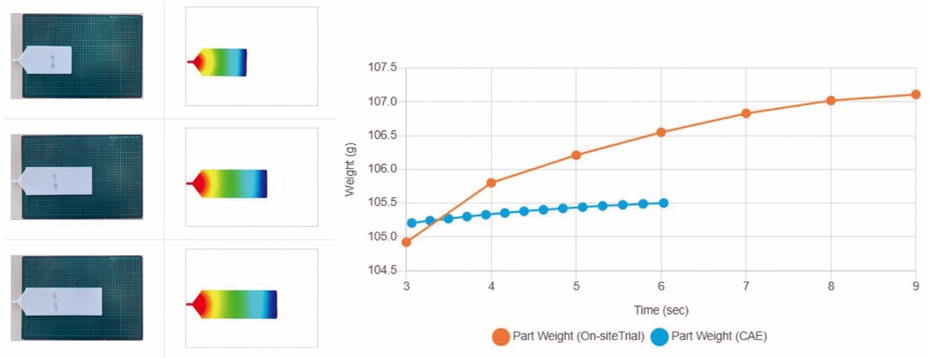
To preserve both virtual CAE mold trial and physical on-site mold tryout data, iSLM further provides unique virtual-physical comparison features. Users can easily compare information such as short shots and molding curves on the web interface. The comparison results can also be recorded on the system for inspection next time, or export a report to the customer.
As today’s industries are generating a much larger volume of data about the physical world, the “digital twin” is necessary and creates corresponding digital systems to store and utilize these data effectively. As the production modes get complicated, the way to manage and maintain such big data also needs to keep evolving. In the race of smart manufacturing, choosing the right tool is vital for enterprises to boost production efficiency and accelerate digital transformation. iSLM is designed to help accumulate design know-how and acquire molding experiences, and transform these digital assets into a valuable knowledge base, bringing additional values and realizing corporate sustainability.
Blog author: Venny Yang, Deputy CEO of CoreTech System (Moldex3D)
Wenny Tsai, Senior Marketing Specialist of CoreTech System (Moldex3D)

