


Valve gate control is a common technique applied in plastic injection molding process due to the fact that it can help shorten cooling time and ensure better surface finish in the gate area. Combining with the sequential injection control, it can further improve molding quality with better pressure distribution and less weld lines. Valve gate and pin movement control involve very complex melt behaviors. CAE simulation tools can help optimize runner layouts and process conditions in the early design stage.
Moldex3D supports analysis with simplified valve gate control as well as detailed valve pin movement simulation. However, the simplified model cannot fully capture the flow rate variation and the effects. On the other hand, the model preparation for pin movement can take a significant amount of time and effort to capture complex flow behaviors around the valve gate. To shorten the modeling time, Moldex3D supports quick model preparation to help users automatically generate the solid mesh for the components required for simulation.
Step-by-step Operation of Quick Pin Movement Model Preparation
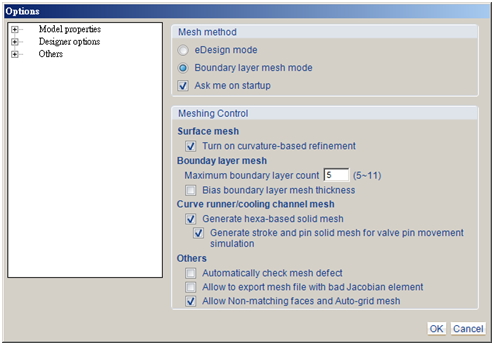
Step 1: Click Generate stroke and pin solid mesh for valve pin movement simulation under the Option setting.
Note: The instructions below use Designer-Project as the example. For Studio, the operation will be somewhat different based on the user interface.
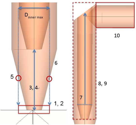
Step 2: Prepare model for Step 2 in the software, and then develop hot runner layout using line elements (using Sketch or drawing lines to assign attributes) and make sure it follows the criteria below:
- The hot runner tip should connect with the part or collinear runner.
- At least the hot runner end (which contacts with the part) needs to be with Valve gate control ID setting.
- Different runner branches with the same Valve gate control ID should have the same stroke gap.
- Proper diameter variation in the tip design is required in order to avoid intersection when the pin closes.
- At the hot runner tip, only one location can be with the same diameter as the maximum inner diameter of the hot runner drop (pin size).
- From the bottom to the top, the diameter of the hot runner tip can only get larger or stay the same.
- From the bottom to the top, the inner diameter of the hot runner drop can only get larger or stay the same.
- All elements of one hot runner drop should be kept collinear and with annular cross section.
- If the Valve gate control ID is assigned to the hot runner drop, the ID should be the same as the tip ID and be continuous.
- The cross section where the top of the hot runner drop connects to the runner circular should be circular.
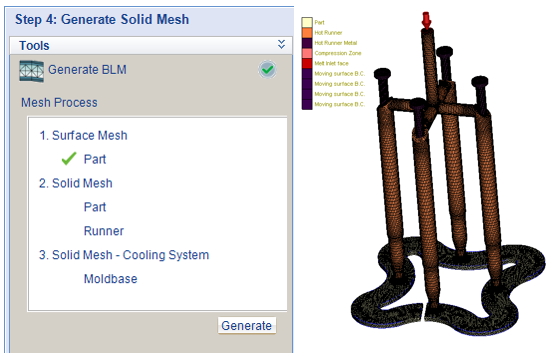
Step 3: Prepare other required model components, including the cavity, inserts and cooling system, and click Generate under Step4 in the interface (or Mesh tab in Studio) to generate solid mesh.
Note: Users do not need to prepare other components of the valve pin. The solid mesh of the pin (Hot Runner Metal) and pin stroke (Compression Zone) will be generated automatically during meshing.
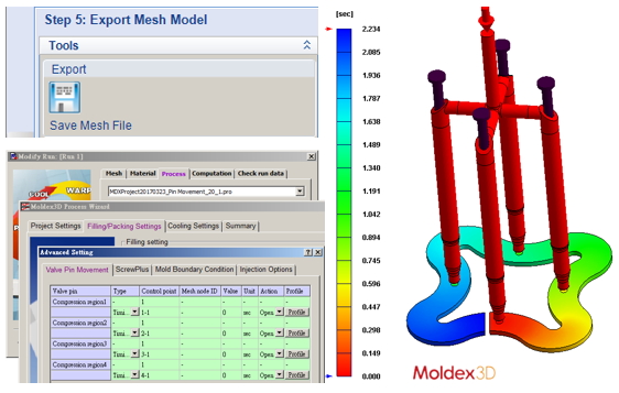
Step4: Export model as MFE and import it into Project (or click Final Check directly in Studio). Users can then setup project and run Flow analysis with Pin Movement simulation. The figure below shows an example of a Pin Movement model and its analysis result of Melt Front Time.
For more information about the Moldex3D product range, please click here >>
This blog was originally posted on the Moldex3D website here >>

