


The challenge of designing winning products is getting more difficult by the day. The choices made in the concepting phase will have a great effect on the manufacturability, performance and the cost of any product.
In this blog, I will explain and show how to utilise Creo combined with Ansys Mechanical solutions can provide some competitive advantages to your product design.
The current trend is to frontload simulation early in design process. This will give the designer insights on products performance on various utility conditions during the design. Currently PTC offers great CAD embedded simulation tools, from generative topology optimization to tolerance analysis. Sometimes, however one needs an expert system like ANSYS Mechanical with broader simulation capability to do the analysis.
As introduction to this kind of early simulation which engulfs usage of Creo Parametric and Ansys Mechanical, we will showcase a traditional welded structure design of an imaginary product. In Creo Parametric one typically creates an assembly with skeleton models, which can be used to guide the placement of components and distribute shapes between models, while guaranteeing the associative update of all CAD data.


The first Skeleton model consists of just surfaces and finished product design consisting solid steel plates as components.
So, how to introduce Ansys Mechanical to this steel structure design?
Here is how, step by step.
Installing Ansys Mechanical interface to Creo Parametric
- Ansys licenses required: Geometry Interface for Creo Parametric
- Preinstalled software: Creo Parametric and Ansys Mechanical
From Windows 10 start menu, select CAD Configuration Manager 2021 R1 and run it using Administrator privileges. Select Creo Parametric Workbench Associative Interface and continue with Next. Indicate the location of Creo Parametric installation and select “Configure Selected CAD Interfaces.
For the Creo Parametric superusers, it is valuable to know that CAD Configuration Manager will create a PROTKDAT row to config.pro, which is at Creo Parametric installation directory. This will start the Pro/TOOLKIT application in Creo Parametric during startup.
PROTKDAT C:Program Files ANSYS Incv211aisolCADIntegrationProEProEPagesconfigWBPlugInPE.dat
One can, on the other hand, modify existing Creo Parametric start-up scripts manually to include the loading of ANSYS Toolkit application. The content of WBPlugInPE.dat is text and it simply points to Ansys installation *.dll and *.exe files. Use of environment variables is OK as well. This makes it possible to include the Ansys Toolkit application only to those users, which require the functionality.
Introduction to ANSYS Mechanical interface to Creo Parametric
After successful installation, one will have new piece of user interface in Creo Parametric.
Named Selection
Named Selection is a ANSYS collector object for points, curves/edges, surfaces etc. You can create these selections in Creo Parametric and utilize them in ANSYS Mechanical.

For example, one might want to select the edges of Creo Parametric model, name them as NS_FIX. Then at ANSYS Mechanical the edges are available for setting boundary conditions, forces etc. The use of Named Selections makes the geometry update process stabile.
AIM
AIM button will transfer the current model at Creo Parametric to ANSYS Discovery AIM.
Workbench
Workbench button will transfer the current model at Creo Parametric to the Ansys Workbench and opens the ANYS Workbench application. The Creo Parametric model is shown as Geometry Simulation System.
Workflow in Ansys Workbench
The starting point for this study is to create Static Structural analysis to investigate initial behaviour of structure. The loads in this study are typical utility loads. In Ansys Workbench environment this analysis is defined by simply dragging the Static Structural system to A2 cell. This will create a new Static structural analysis and connect it to Creo Parametric geometry import. Thus, making the geometry update possible from Creo Parametric.
Second step is to study is to investigate how the model will lose its stability at loading conditions defined at Static Structural system B. This is investigated by dragging an Eigenvalue Buckling system to Solution of Static structural B6, thus connecting these systems.
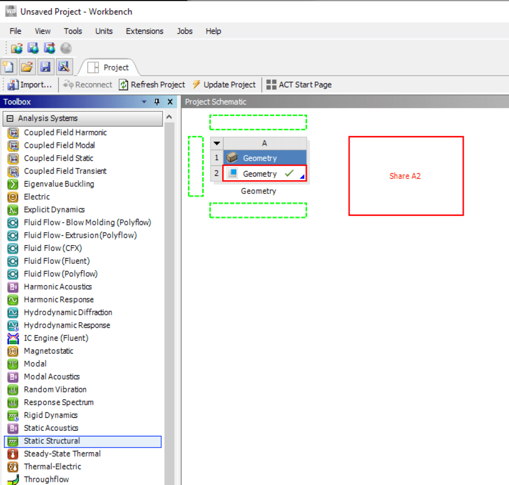
Geometry system with Creo Parametric geometry at cell A2. To utilize this geometry to static structural FEM in ANYS Mechanical, just drag Static Structural system to cell A2. One can update Creo Parametric geometry also from Ansys Workbench, just by clicking A2 and Right Click and select Update From CAD.
From Eigenvalue Buckling one will get a Load Multiplier for each buckling mode. The actual load, which is required to lose of stability. You may consider Load Multiplier as a safety factor for load in linear buckling. Therefore, the actual load required to buckling can be calculated just by multiplying Load Multiplier with used load. This is done at last step of our analysis. Eigenvalue Buckling analysis will also give the buckling modes – i.e., describe how structure would start to deform, should the loading be sufficiently high. Please note, that linear buckling assumes perfect geometry without any deformation etc, so results are “descriptive”.
The last portion of our analysis is to study the behaviour of our structure under load which is greater than buckling load. Also, we want to pre-deform the model according to Eigenvalue buckling mode results, so that model is prone to lose its stability due geometrical imperfections rather than ideally having correct geometry.
This last connection is done by first creating the standalone Static Structural analysis system and then connecting the Eigenvalue buckling to it, by dragging the solution (C6) to Model (D4). Also connect the Engineering data cells.

The severity of geometrical imperfections introduced by mode shape can be adjusted by taking Solution cell of the buckling analysis (C6). Right Click and select Properties. This lets you choose the scaling factor and model shape going to last structural analysis. Typically, one will choose model 1.
Just a note, that this chaining of analysis is not a new functionality in ANSYS Workbench. The ease of use is getting better by each release, thus enabling the full benefits of simulation to larger user groups. For example, from release 17 onwards one has had the possibility to create post buckling in Workbench environment without using MAPDL and command UPCOORD.
The last simulation system (D) is used to calculate the structural behaviour when loading exceeds the buckling load. For it, user must reapply the forces and constrains to model. Typically, the computation is done using multi step loading, large deformation option and material plasticity.
Recent development in Ansys Mechanical meshing
During the years one point of manual effort has been meshing the structure. The root cause has been surfaces from CAD application, which are intersecting. The mesh generation did either require splitting of surfaces and typically lose associativity to CAD or use of specific CAD modelling methodology. The alternative route was to use contacts and generate mesh connections using it. This approach has it downsides when it comes to computational efficiency and result interpretation.
Despite the route used, some difficulties were common, while trying to match element nodal point locations on different meshes. Therefore, a manual effort either at Creo Parametric or at Ansys has been required to get nice conformal meshes.
This has however changed for good. At ANSYS Mechanical 2019.1 one can select Mesh> Batch Connections > Mesh Based Connection = YES, which will lead to conformal mesh. The Mesh sizing option Capture Proximity = Yes is also helping to get quality meshes. This is global setting. In the Ansys Mechanical 2021 R1, we have Connections control in Ansys Mechanical which contains all global Mesh Based Connections controls. This Connect control can be used where needed instead of global setting.
All of this helps a lot when it comes to delivering geometry from CAD application to Ansys Mechanical.

Parametrization in Ansys
Creo Parametric is parametric 3D CAD starting from name of application. The Ansys Mechanical has similar abilities to script simulation models for design alternatives.
The best news is, that both words can co-exist.
From Creo Parametric all dimensions and parameters will be available in Ansys Mechanical if:
- The naming is beginning with ANS or DS
- The Workbench options are set accordingly
You may modify the importable objects in ANSYS Workbench, by selecting Tools>Options and Geometry Import> Basic Options.

These options will import solids, surfaces and curves from Creo Parametric to ANSYS Mechanical. The named selections, which begin with name of NS & parameters and dimensions with name beginning with ANS or DS will be imported.
The CAD based attributes are available, but not shown by default. The CAD Parameters can be set available to ANSYS Design Exploration environment, just by clicking corresponding model at Ansys Mechanical Geometry node.


This same principle applies to computation results as well. For example, at structural analysis one can select Equivalent Stress (von-Mises) results and pick check box for Maximum stress.

Additional samples for parametrizable things in ANSYS include shell element thickness, material, beam element cross section etc.

All selected parameters are available in Parameter Set view where one can create additional design points based on parameter inputs. Should the parameters include Creo Parametric dimensions, then the Creo Parametric model will be altered, ANSYS Mechanical models updated, and all relevant results computed.
This is a great way to vary the Creo Parametric model and study the effects of component dimensions etc. for structural performance. Additionally, one can create new geometry or modify existing and all work done in ANSYS Mechanical environment will be updated accordingly.
I hope you’ll find this useful, and for more information on how PDSVISION can help you with your mechanical design why not visit our dedicated pages for more, or get in touch direct – here.
Regards
Mikko

